Introduction
I miss working with my hands. Everything I do in my daily work is “virtual”, I mostly imagine things and when a good thought appears, I try to put it into words, or code in light patterns on a flat surface in front of me.
Even this attempt at philosophizing above you can see I need a project. A physical project.
I always wanted to build a keyboard. It makes sense to craft something that you use everyday. After all this is one of only few interfaces I have to the virtual world I am working with. A regular keyboard would be too boring, so I decided I will build a super ergonomical split keyboard. That’s actually two keyboards - one for each hand.
After a lot of searching I have settled on building the Redox keyboard. See the orignal repo here Redox Keyboard. All credit goes to the original author - Mattia Dal Ben.
I chose Redox since I wanted a minimalist split keyboard, I liked the OG ergodox, but it seemed a bit dated. A lot of the other split keyboards seemed very restricted. Redox seemed like a very well balanced design. I as well liked the idea of transferring a lot of functions to the thumb cluster. After using the keyboard for 2 weeks I already have couple of ides how to change the layout. People are right, once you get into the world of custom keyboards you will never stop tinkering.
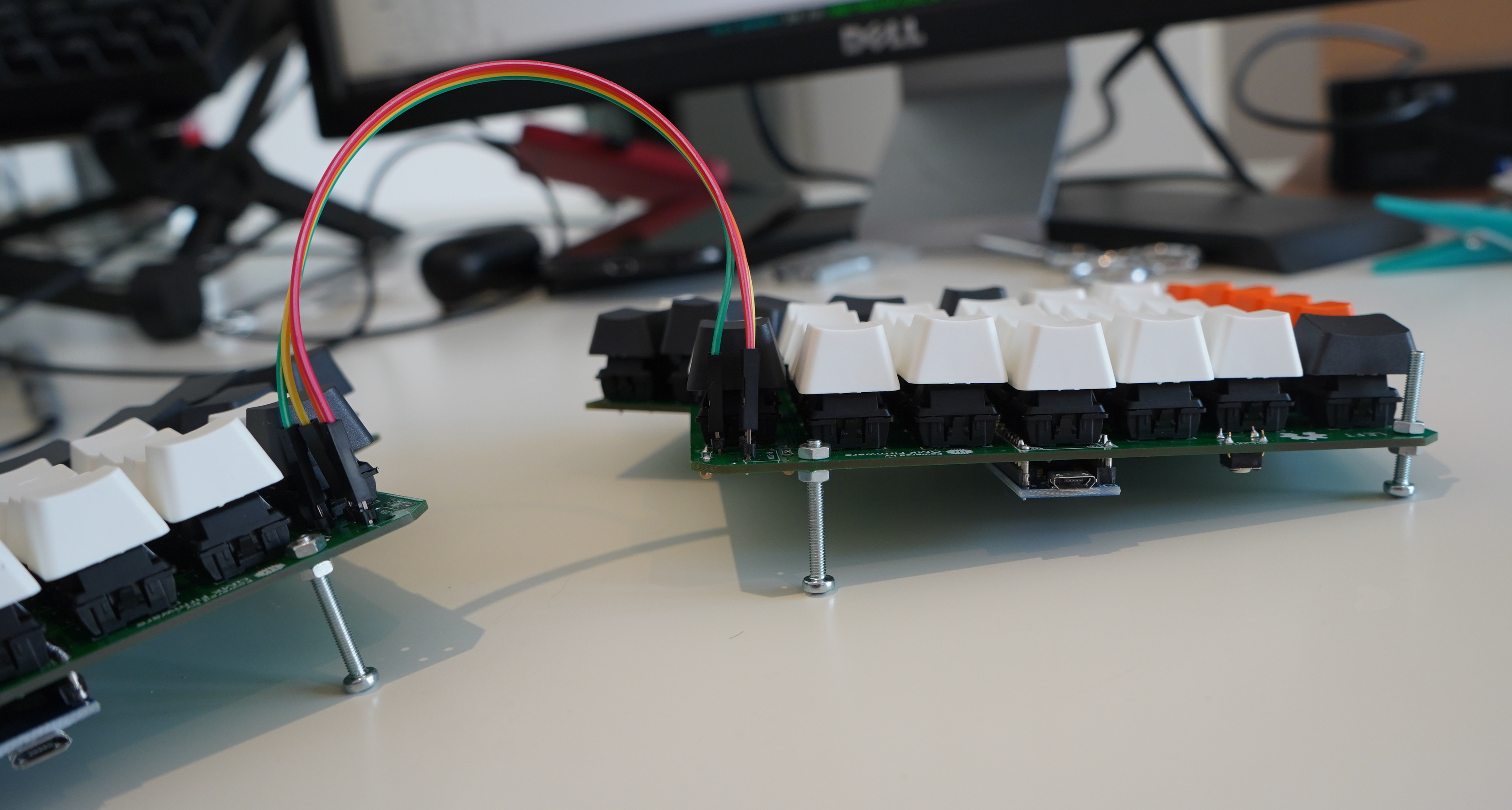
This is going to be a short build guide. First a picture of a finished build.
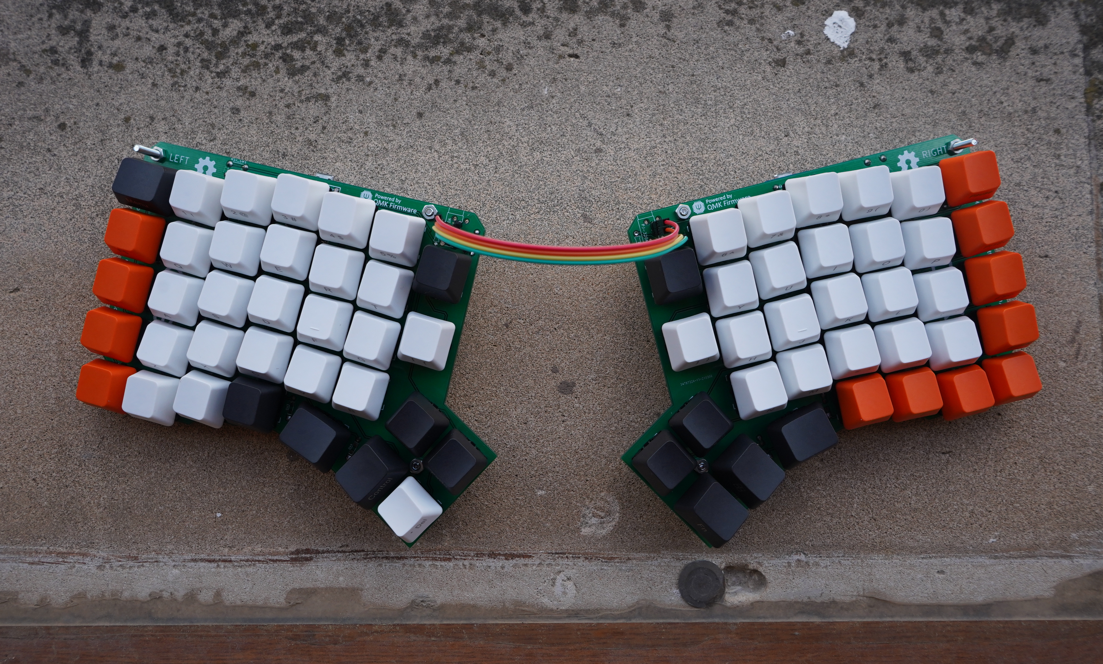
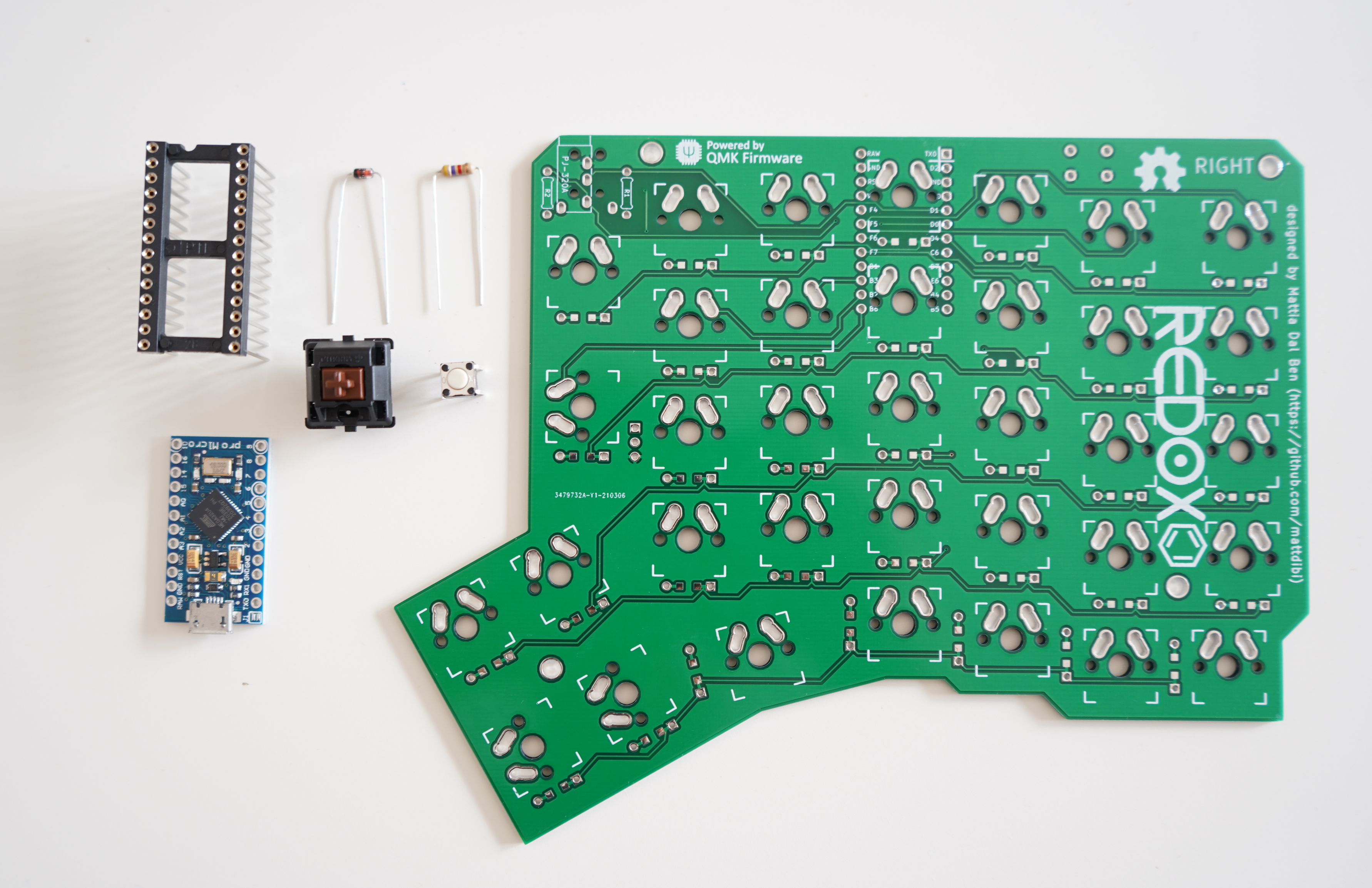
The components are very simple. You need switches and a microcontroller - the brain - that will check if a switch is pressed and send a relevant command to the computer. The rest of the components support the above. Here is a full list, taken from original Redox design, and slightly modified by me.
| Qty | Item | Notes |
|---|---|---|
| 70 | Cherry MX compatible switches | I chose Cherry MX Brown |
| 2 | Redox PCBs | Printed a custom one |
| 70 | 1N4148 diodes | |
| 2 | 4.7 kOhm resistors | |
| 2 | Through hole momentary switch | Dimensions 6mm x 6mm x 4.3mm |
| 2 | Arduino Pro Micro compatible microcontrollers | |
| 1 | USB micro cable | |
| 70 | Cherry MX compatible keycaps | 10x 1.25u keycaps, 6x 1.5u keycaps, 54x 1u keycaps |
| 2 | Microcontroller socket |
The main tool that you will need for this project is a soldering iron. I have recently moved countries and so I had to buy a new one. A decent pen soldering iron with temperature regulation, a bit of solder, and side cutters was about 20€.
Gathering all materials
I have gotten then pro micro clones from aliexpress. I bought 5 since I wanted to have couple more to play with and destroy. I plan to make the keyboard work with USB C. USB C EVERYTHING! I bought the sockets already. Stay tuned for a post about the modification.
Printing PCBs
The most difficult - except for keycap in perfect color - part to procure was the PCB. The shipping from all the available shops was horrendously expensive. So I thought I’d try and have the PCB printed, as I have never used such service.
Many many years ago when we were playing with making various electronic contraptions with my brother we made the circuit boards ourselves. That was a two stage process. We bought blank panels of laminate with one side covered in copper. You’d then draw the paths you wanted with a permanent marker. That marker would protect the copper from being dissolved by acid. That was the next step, dunking the board in the acid bath for couple of hours. The timing was very important, if you left the board too long in the acid it’d eat through the marker and ruin your design. The process was very finnicky, and required a lot of trial and error.
Back to the present day. I am amazed. For dirt cheap you can order beautiful. And I mean beautiful PCBs. Two-sided. With a silk screen. The PCBs are reversible, which means I could print 5 - the minimal number at the vendor I chose: JLCPC - identical ones. And then use two of them, the PCBs are then flipped between left and right hand sides.
Let’s start building
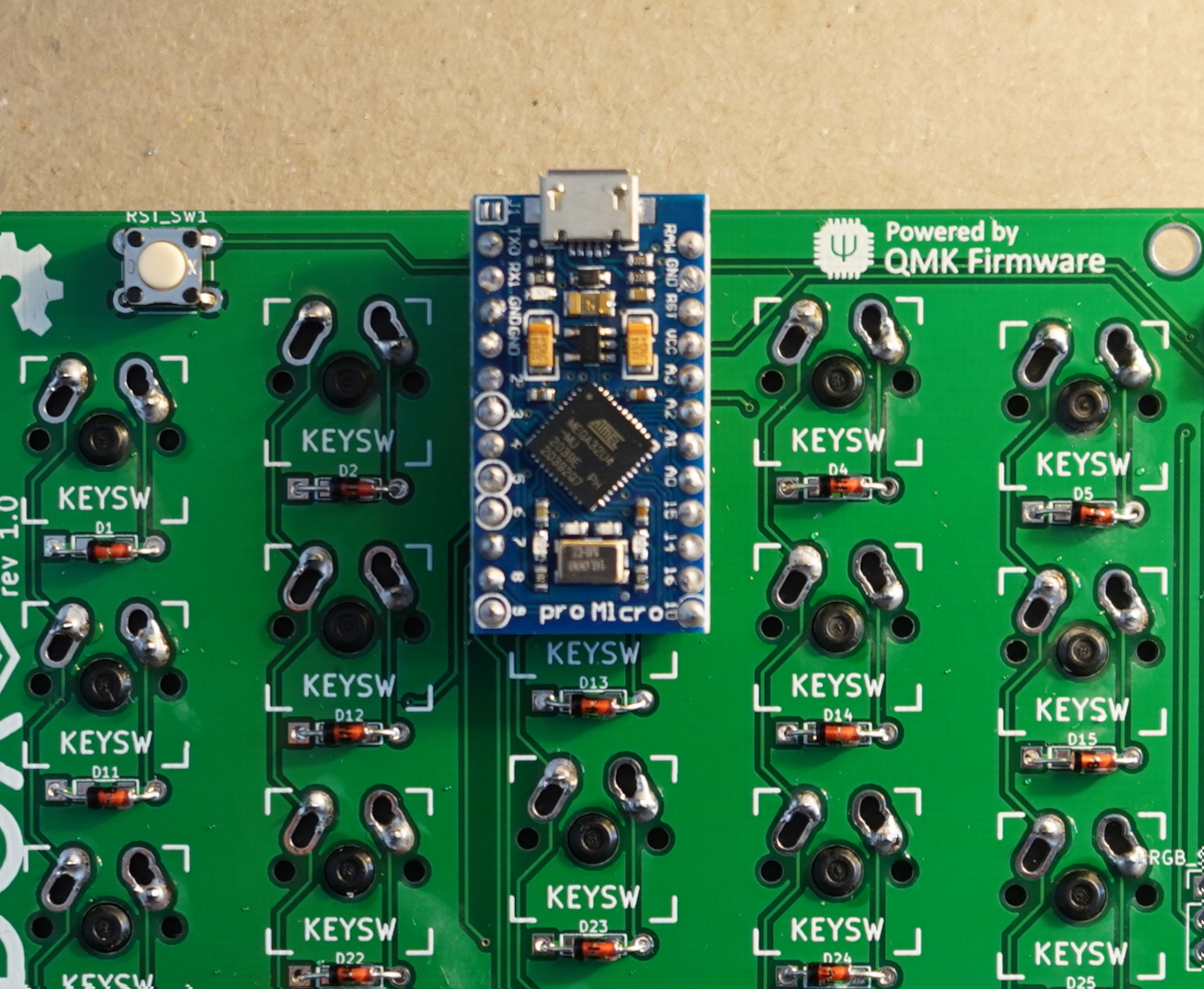
The order of operations is important. If you solder components in the wrong order you will block access to the areas for soldering others. The very first component we’re going to solder on are the diodes.
Once soldered, cut all of the diode legs. Save them, we will use them later.
Next, solder:
- the reset switches.
- the resistors (only on the left hand part)
The original guide calls for installing the TRRS jack now. I don’t like the idea of a headphone cable connecting the halves. I always disliked the headphone jack and the socket. Plus the cable is not resistant to hot plugging. My plan was to install an RJ9 socket and cable. However the that would require installing the socket on wires and mounted in the case. Right now I am rocking the keyboard naked. I have opted to connecting the halves with standard pin connector.
Pro Micro
I think it makes sense to mount the pro micros in a socket. The next step then is soldering in the sockets. I got the precision kind, but a regular one will work fine as well. I didn’t have small enough pins to solder to the pro micro to fit within the precision socket so I used the offcuts of the diode legs. Place the pro micro on the socket so that the holes line up. Using needle nose pliers slide a cut off diode legs through the pro micro into the precision socket. You will feel when the wire is properly seated. First solder the corners and then fill in the rest. Now you can carefully pry off the pro micro from the socket.
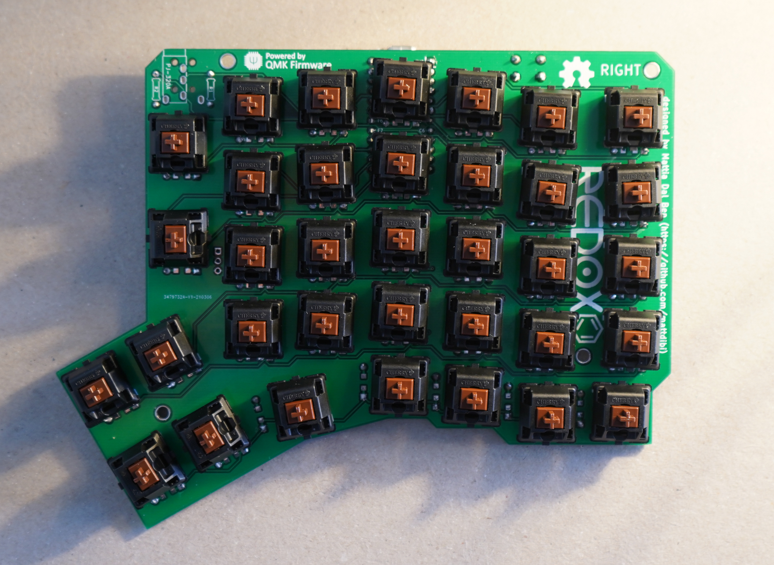
Switches
Finally we arrive at the best part - soldering the switches. You will need to flip the PCB first. The switches go on the opposite side from all the other components.
I first soldered corner switches and then filled in the rest. Without a case, or a switch plate it was hard to solder the switches evenly. Once all switches where in place I tried to reflow the solder one by one and rotate the switches so they were more even but I wasn’t greatly successful. Being so close to the end I just went with it and it turned out it was not really a problem. You can barely see it when you look at the keyboard straight down (and you never do that) - and you certainly can’t feel it with your fingers.
Tenting
You definitely need to tent the keyboard. I am planning to do it properly with a custom case I am designing. Right now I have achieved it with screws through the case mounting holes in the PCB.
Software - QMK
The keyboard is using the fantastic Quantum Keyboard firmware - QMK QMK already contains the configuration and default keymap for redox.
More or less I am following the instructions in the original Redox repo. But I found I had to additionally configure some defaults for everything to work.
First, Install QMK - Official guide
Configure QMK
I am not using the LED underlight so I want to use I^2C for the halves communiction QMK I2C
|
|
As you can see I opt in to setting the handness of the halves by using EEPROM - read about the details in the QMK guide <https://docs.qmk.fm/#/feature_split_keyboard?id=handedness-by-eeprom>_.
Now onto flashing the pro micro. Connect the left half (the master) to the computer, and execute in the qmk directory.
|
|
After each command you will need to press the reset switch on the board. You should see a success message.
Now for the right half:
|
|
$(COM_PORT) with your port where the pro micro is attached to. You can figure that out for example from dmesg.This is it! You can start using the keyboard with the standard keymap. You can explore it here: https://config.qmk.fm/#/redox/rev1/LAYOUT
Keymap
Now onto the fun bit of customising the keymap. Adding layers and all this. I have to be honest with you. After two weeks with the new keyboard I am still relearning how to actually touch type. The ortholinear layout is as well a bit of a learning curve. I have adjusted the default keymap a little bit. The procedure is as follows.
- Go to https://config.qmk.fm/#/redox/rev1/LAYOUT and make your changes.
- Download the
jsonof the keymap > qmk flash ../redox_rev1_layout_mine.json
What’s next?
I have two modifications I want to make.
First is resoldering the micro USB on the pro micros with the USB C.
The second is building a case. Although the keyboard looks fantastic with just the PCB, the case will provide a much needed wrist support.